Sunday, August 23, 2020

MMC interface Project

Note: This project design is for use with OS-9, and so there is no support for BASIC.

After working on the by Color Computer to IDE interface I thought it would be much cleaner to avoid having a hard drive, external power supply, wires, etc.  I started working on this idea in late 2002 and into 2003.

My first thought was to use a compact flash card, but it seemed complicated with all of the pins.  I wanted something more simple to connect to the Color Computer.  I looked into a new format called MMC or MultiMediaCard.

MMC Card example

Due to the complexity of the connection, I knew I would need something more advanced than discrete logic, as I had used on my IDE hard drive project.  At the time I had been messing around with AVR microcontrollers from Atmel and so I investigated the use of their CPLD parts to design the logic needed.  At the root of the project is a SPI that translates from serial bits to parallel bits required by the Coco.  One more issue was that MMC cards needed 3.3V VS the 5V that is available from the Color Computer bus.

The part I chose for the project as an Atmel ATF1508ASL.  The part had the I/O that I would need to interface two MMC cards and the Color Computer bus.  Along with the CPLD there were two other parts required.  One part was to convert from 5v to 3.3v and I chose to use a 74hc245 to do the conversion.  For the necessary 3.3V I used a LM2937-2.5.

The board took some pretty severe wiring to complete, here is the result.


To connect to the Color Computer I used my IDE interface board with a 40 pin header.

OS9 Drivers in place.  Note: The cards do not support booting to OS-9


Color Computer Slot Extender

Using this board you can extend the cart slot out to a breadboard or make a y-cable.

Link to download all files for this project.

Project Creator: "Little"John Eric Turner and "Big" John Robert Turner

Schematic

Board photos


Four Chip 512k Upgrade for the Color Computer 3

NOTE: These memory chips require a 512 refresh cycle, while the Coco only provides a 256 cycle refresh for DRAM refresh.  This makes the board only work as a 256k board.  There are many other upgrade options available now and this solution is not optimal.  I am leaving this project up for reference purposes.

The Problem

Back in 2003, I was trying to figure out why one of my 16 chip memory board had stopped working for some reason.  I actually solved my problem by wiring up a couple of 256k SIM modules using a schematic I found on the internet.  That got me thinking about trying to create a whole new solution for memory upgrades for the CoCo 3.

Over the years I have collected many old ISA cards, always thinking about ways to wire them up for use on the CoCo.  This time around I found it easier just to take the memory chips of some of the 512k -1MB boards and using them for a 512 memory upgrade project.

DRAM DIP pinout

Part number GM71C4256A-80

The Solution

I needed a reason to design my own board and have a couple of them made.  Making my own boards sounded like a great challenge as I have never tried anything like this before.  Checking my latest edition of Circuit Cellar I found several programs available for use in creating circuit boards.  A program from Autodesk EAGLE seemed like a good fit for this small project.  It includes a free edition that even handles auto-routing.  The board size in the free edition is rather limited and there is also a 2 side limit.

Board layout

Board schematic


The Result

After having two boards manufactured I was ready to test out the final product.  I pulled the memory chips off of the ISA VGA cards and added them to my new four chip memory board.  I plugged in the memory board into my CoCo 3 and crossed my fingers and, success on the first try!  After further testing, I found the issue where this board is only working as a 256k board.  Due to the board not working as a 512k board I could no longer use it in my system.

Front and rear board photos


Coco 3 with the memory board installed

Note: I have to trim the board a little by hand so it would fit

Link to the EAGLE project to make this board

Autodesk EAGLE design project


Sunday, August 2, 2020

When SALT goes bad

When SALT goes bad

Initial problem

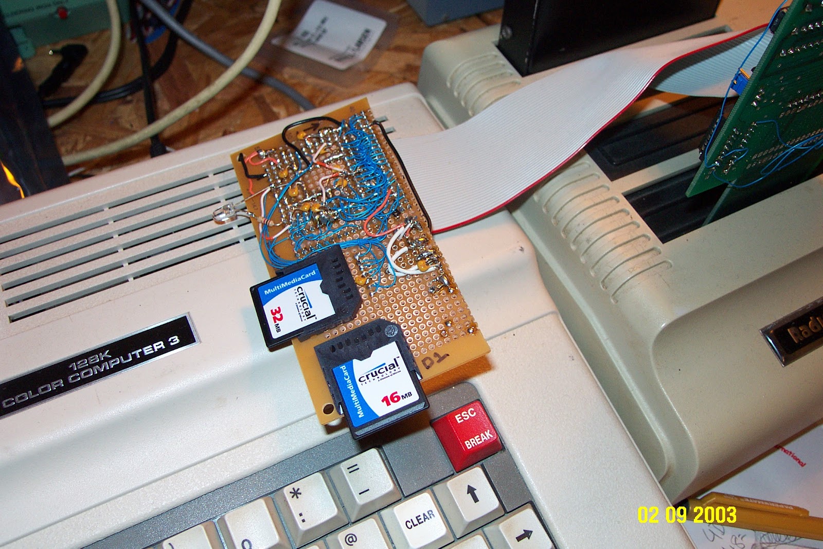
While trying out my new CoCo SDC with my Color Computer 3, I found some strange issues.  Symptoms included garbage on the screen while turning on, garbage after hitting reset, computer not initializing with any text.  Any cartridge inserted would cause the system not to display any video.  I also noticed something odd; the usual double click of the cassette relay when power was applied was missing.  All I heard was a single click, and pressing the reset button did not generate any clicking of the relay.

I tried reseating the GIME, swapping out the memory card for a working 512k board, replacing the electrolytic capacitors over the entire board, and finally looking around for any anomalies that might explain why my Color Computer 3 was not working correctly.

The basic troubleshooting I had done to this point had gotten me nowhere, I needed to get out the service manual and a digital meter to see what was going on.  My first stop was to validate the 5V power source for the board.  As I turned on the machine and connected the meter, I was shocked to see a reading of almost 6.1v on the 5v line.  No matter how many times I checked, it was still 6.0V - 6.1V across different locations on the board.  I also noticed that the SALT chip, the Motorola SC77527P, was heating up very quickly after I turned on the power.

Thankfully I had other Color Computer 2 and 3 machines to open and inspect.  I quickly found that other Color Computers had regular readings for voltage, and the SALT chip was not getting hot to the touch.  I knew that the SALT chip was part of the problem, and I started to get very concerned.

Following the service manual

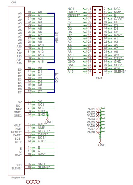
I already knew that the 5v line was 6V, this quickly moved me to ‘D’ in the following flowchart.

Next was to check the Emitter and Collector of Q1, where I found a difference of 10v to 6v.  Unfortunately, my computer was suffering from a defective SALT chip.

After opening three other Color Computer 2 models I had lying around, I found the one I needed, this unit had the SALT chip socketed, and discovered my doner!

How to remove the defective SALT chip

Removing the chip without damaging the Color Computer 3 board was going to be a challenge.  Here are some of the things that made it a success.

By clicking the links below, I may receive a commission.  Using these links has no impact on the purchase price.  Thanks!

  1. Weller soldering iron with a fine tip and temperature control.  I preferred to use 800 degrees for this job.

  2. Lots of solder flux.

  3. Solder wick.

  4. Solder sucker


To get started, you should clip out the old chip with a pair of dikes, this should reduce the chances of damaging the circuit board due to too much heat.  Notice pins 9-16 are clipped below in the photo.

After cutting out all 16 pins, you should be able to remove the defective chip easily.

Carefully remove the pins one by one and then clean the old solder from the holes so the new part can be installed appropriately.


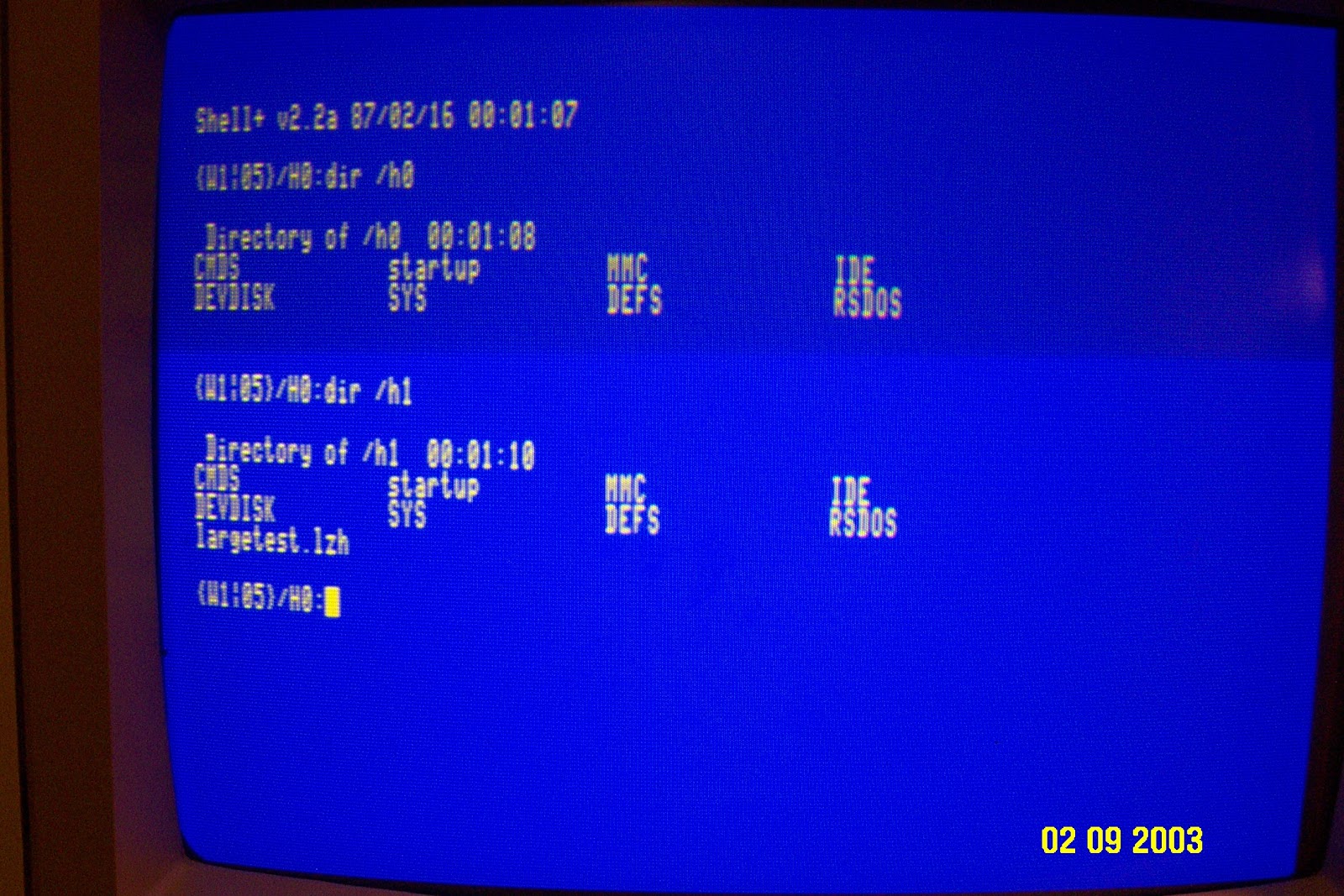
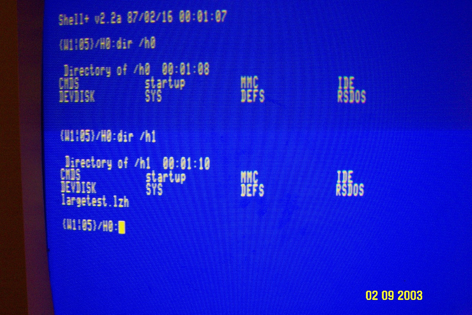
I was sure to install a good quality chip socket before using the new replacement chip, this was a lot of work, and I don’t want to be soldering this section of the board again.  Once I assembled the board and did a quick test, I could tell that things were back to normal.  Hopefully, the 6v across the 5v line of the board did not cause any long term damage, I have not had the time to go through and test everything to be sure.  I can say that the CoCo SDC was working great, and I was quickly able to boot to Nitros-9 and try out my system again.

Bad SALT chip


MMC interface Project

Note: This project design is for use with OS-9, and so there is no support for BASIC. After working on the by Color Computer to IDE interfac...